
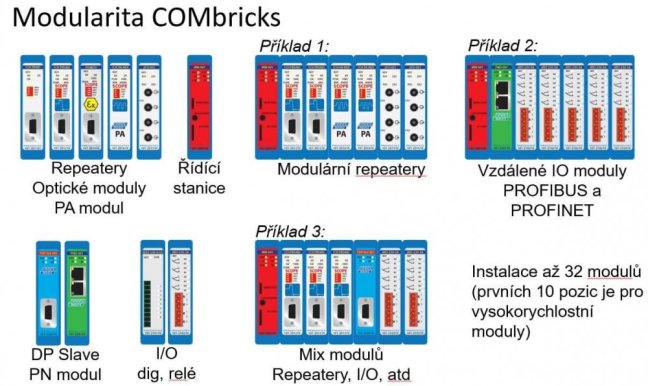


ComBricks PROFIBUS Fiber Optic Ring Module – Single-Mode

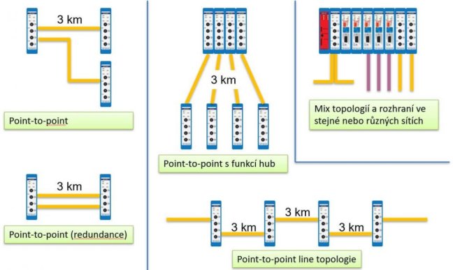
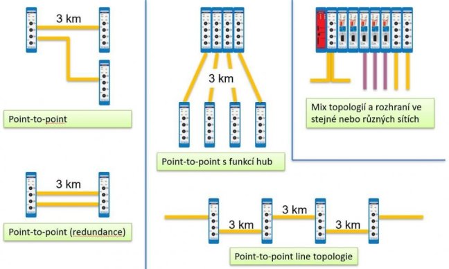
ComBricks module for singlemode optical PROFIBUS signal transmission via ring, point-to-point, line, star or hub topology. Signal transmission up to 30 km via singlemode optical cable. Suitable for environments with high electromagnetic interference. More
Code: 101-201531
ComBricks module for singlemode optical PROFIBUS signal transmission via ring, point-to-point, line, star or hub topology. Signal transmission up to 30 km via singlemode optical cable. Suitable for environments with high electromagnetic interference. More
Code: 101-201531
ComBricks PROFIBUS Fiber Optic Ring Module – Single-Mode
This multifunctional module is designed for PROFIBUS communication over singlemode optical fibers. It enables the creation of redundant ring topologies and the interconnection of devices over distances up to 30 km. The module is particularly suitable for applications in environments with high electromagnetic interference, such as water treatment, mines and tanks.
Key Advantages
- Signal transmission up to 30 km
- Resistance to strong EMC interference
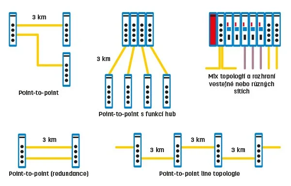
- Ring, point-to-point, line, star or hub topologies
- Online diagnostics and management via web interface without the need for additional software
- Fault indication by LEDs and e-mail notifications
- Galvanic isolation of segments
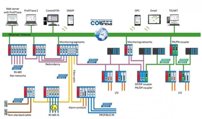
- Option to connect optical and copper segments (in combination with other ComBricks modules)
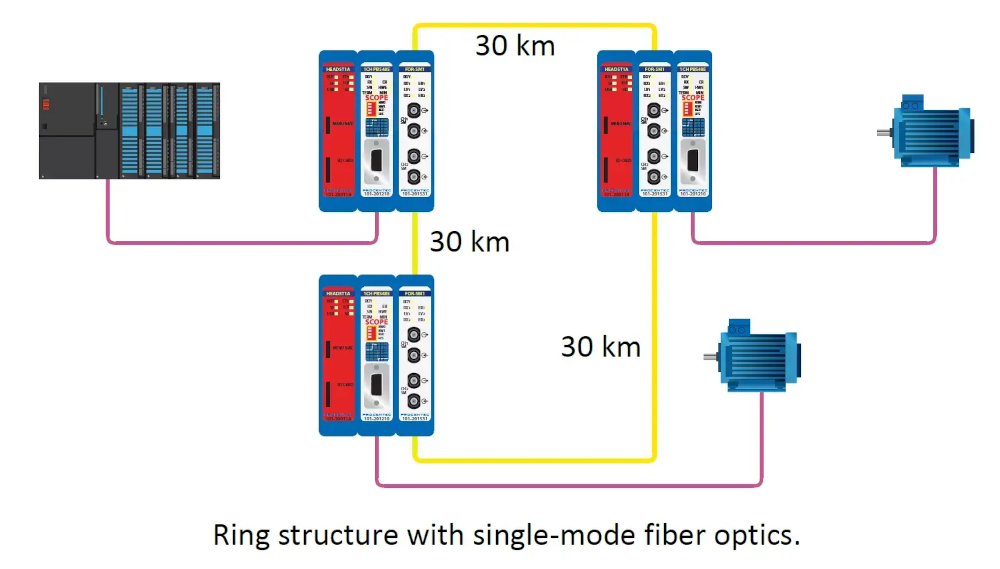

How the ComBricks PROFIBUS Fiber Optic Ring Module – Single-Mode Works
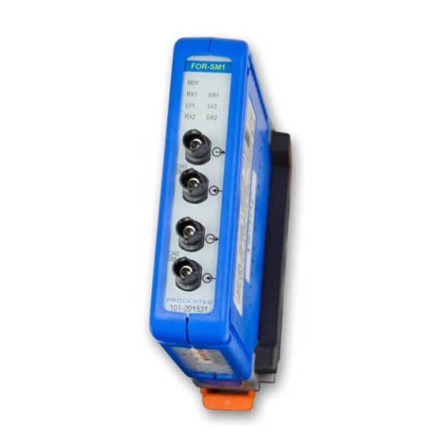
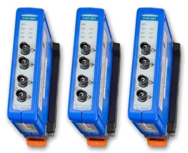
This module is specially designed for optical data transmission in PROFIBUS networks. In the Single-mode (SM) variant, it uses singlemode optical fibers that allow signal transmission up to 30 km (depending on the baud rate), e.g. when connecting large industrial sites or backbone networks for data communication. The optical fibers can be easily and securely connected via four ST/BFOC connectors – 2 for each channel.
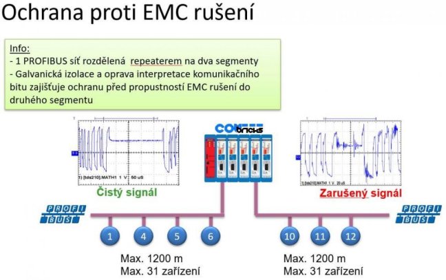
Two galvanically isolated channels allow the connection of two independent PROFIBUS DP segments. The isolation between channels ensures higher communication reliability and eliminates interference between segments.
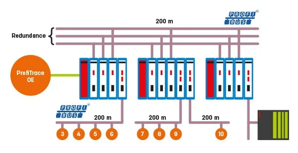
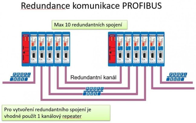
It supports the creation of redundant ring topologies that enhance communication reliability. Redundancy ensures that even in the event of a fiber break or segment failure, the network remains operational, and the operation is not interrupted. Additionally, the module provides galvanic isolation between segments, contributing to network protection against interference or faults.
Before using the ring topology, the manufacturer recommends updating the head station firmware to version 1.288 or higher to ensure full support of all module functions.
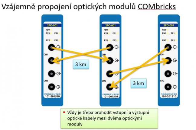
In ring topology, channels must be connected CH1 to CH1 and CH2 to CH2. Only in the case of an uneven number of modules may CH1 and CH2 be connected, but only once in the entire ring.


ComBricks Module Configuration
Module settings are performed using DIP switches on the bottom of the module. The advantage is that the ComBricks module settings are immediately visible at first glance. The second configuration option is via the ComBricks web interface.

Network Diagnostics Options
These optical modules also provide excellent diagnostic capabilities. The operator standing directly at the device can use the LED indication.

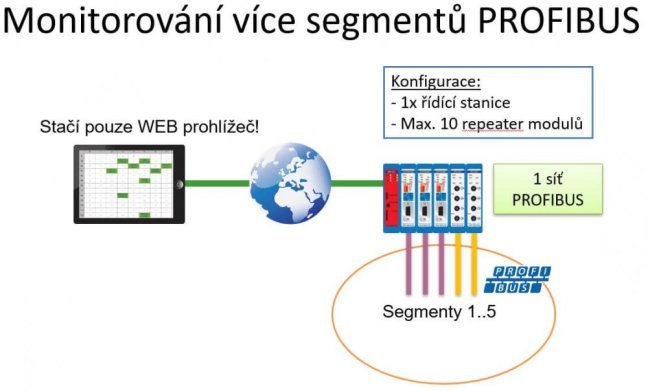
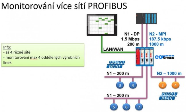
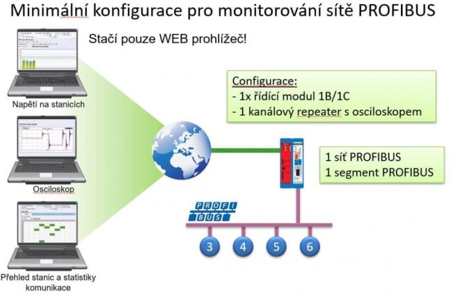
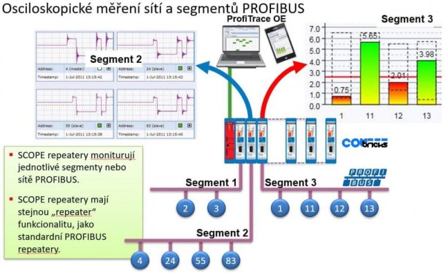
Another option is remote diagnostics via the web interface using the built-in ProfiTrace OE functions. Thanks to this, information is provided from all modules, including the intensity of the optical signal and the status of the ring topology.
The optical signal intensity is displayed in three levels:
- Signal is OK,
- Signal low,
- No signal.
For ring topology, two states are indicated:
- Ring OK,
- Ring failure.
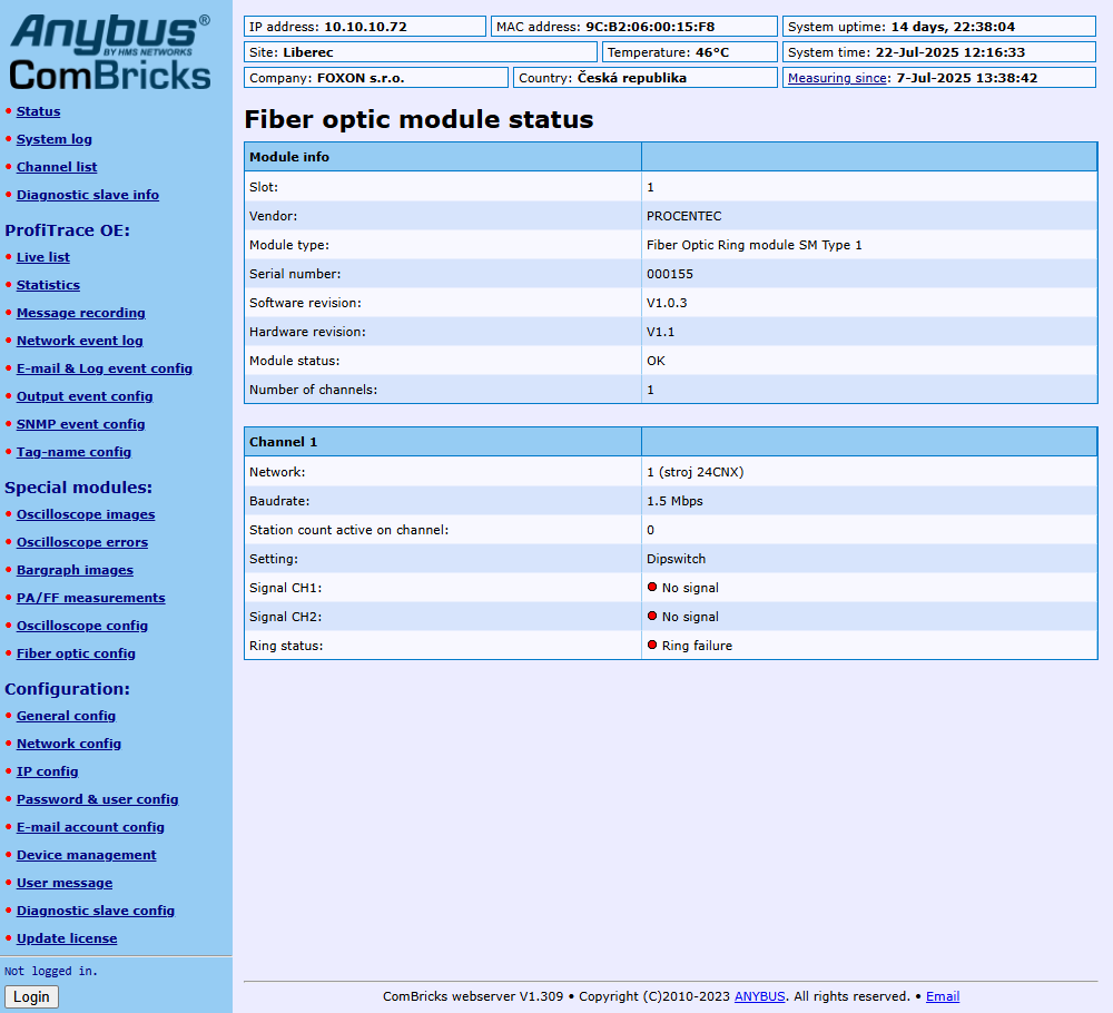
Using advanced e-mail notification settings, the ComBricks system can alert when a fault occurs, signal intensity drops, or the ring topology is damaged. Based on configured triggers, events can be logged on the memory card and displayed on the web interface under the Network Event Log tab. These triggers can be set for any change or only when the state worsens.
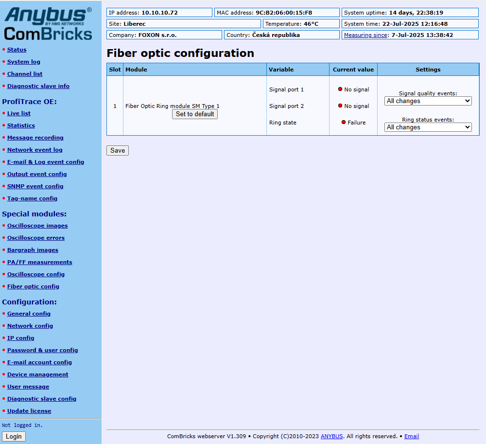
Depending on the configuration, an e-mail will be sent, a log recorded, or both upon events.
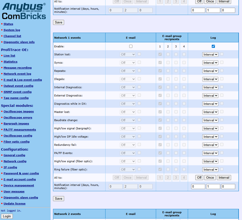
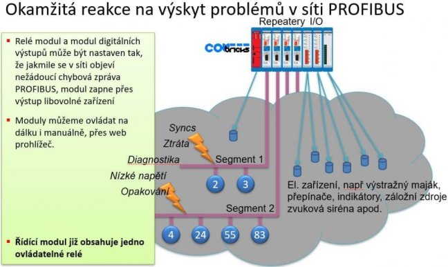
Additionally, it is possible to configure an output on the head station or an added module with digital or relay outputs based on the event. The output can, for example, activate a signal beacon or an input in a PLC control system.
Highlighted items are mandatory.

Training PROFIBUS - Basics, Diagnostics & Network Troubleshooting, 2 days
961,52 EUR Inkl. MwSt.

Diagnose, Reparatur und Monitoring von PROFIBUS Netzwerken
ab 361,76 EUR Inkl. MwSt.
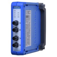
ComBricks PROFIBUS Fiber Optic Ring Module – Mixed-Mode
321,30 EUR Inkl. MwSt.
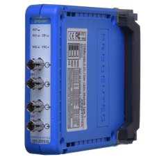
ComBricks PROFIBUS Fiber Optic Module
978,18 EUR Inkl. MwSt.
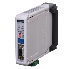
PROFIBUS repeater ComBricks with oscilloscope for 1 PROFIBUS segment
1 286,39 EUR Inkl. MwSt.
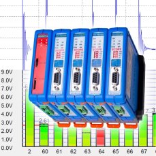
ComBricks Advanced set for permanent measuring of max four PROFIBUS networks / segments
7 101,92 EUR Inkl. MwSt.
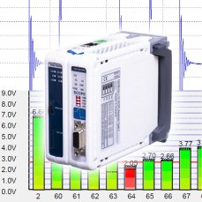
ComBricks Standard set for permanent monitoring of one PROFIBUS network / segment
2 986,90 EUR Inkl. MwSt.
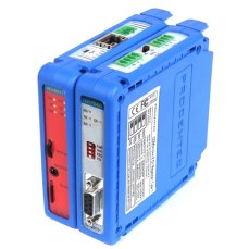
ComBricks Basic set for permanent monitoring of one PROFIBUS network / segment
2 261 EUR Inkl. MwSt.
Related products8
Training PROFIBUS - Basics, Diagnostics & Network Troubleshooting, 2 days
961,52 EUR Inkl. MwSt.
Diagnose, Reparatur und Monitoring von PROFIBUS Netzwerken
ab 361,76 EUR Inkl. MwSt.
ComBricks PROFIBUS Fiber Optic Ring Module – Mixed-Mode
321,30 EUR Inkl. MwSt.
ComBricks PROFIBUS Fiber Optic Module
978,18 EUR Inkl. MwSt.
PROFIBUS repeater ComBricks with oscilloscope for 1 PROFIBUS segment
1 286,39 EUR Inkl. MwSt.
ComBricks Advanced set for permanent measuring of max four PROFIBUS networks / segments
7 101,92 EUR Inkl. MwSt.
ComBricks Standard set for permanent monitoring of one PROFIBUS network / segment
2 986,90 EUR Inkl. MwSt.
ComBricks Basic set for permanent monitoring of one PROFIBUS network / segment
2 261 EUR Inkl. MwSt.